1
Ceiling Light Wall Switch Kit
User's Manual
Enclosed you will find
♦ ID Wall Mount Control
♦ Double-SidedTape/Screws
(for mounting)
♦ ID Socket Adapter
The GE SmartHome™ Plus advantage
Any transmitter in the GE SmartHome™
product line is capable of controlling every
receiver-the ultimate in home convenience.
Control any number of light fixtures or a ppliances
from up to 150ft* away by
choosing the transmitter and receiver
combination that best suits your needs.
lIStEO
51137-2
12/5/06
General Electric Company
and is used under license to
Jasco Products Company LLC,
311 N.W. 122nd Street,
Oklahoma City, OK 73114
www.jascoproducts.com
^WARNING
Risk of electric shock
• Turn power off before inspection,
installation or removal
• Keep children away
• Use indoors only
• Do not use in wet locations
• Screw in securely
Risk of fire
• Do not exceed electrical ratings
The following GE SmartHome™ transmitters Isold separately) can control THIS receiver:
ik>-
$
Key Chain Remote
RFIOOTXPS
Wireless
Remote Transmitter
RF102TXPS
o
raOOK/WPS PF6I3TX
The transmitters above can also control the fbllcw/ing GE SmartHome’” receivers (sold separately):
/ndoor
Recem Module
RnOORXPS
Outdoor
Recem Module
RnOSRXRS
include'^'
Socket Adapie(
Rfimm
Q
Wall Switch
RF102RXPS
IMPORTANT! These devices are NOT compatible with devices from other systems.
You must purchase GE SmartHome™ transmitters and receivers to ensure compatibility.
To extend the range ofthe
transmitters and receivers
inyour^stem,usethe
GE SmartHome™
Range Extender
(sold separately).
Range Extender
RFlOORm
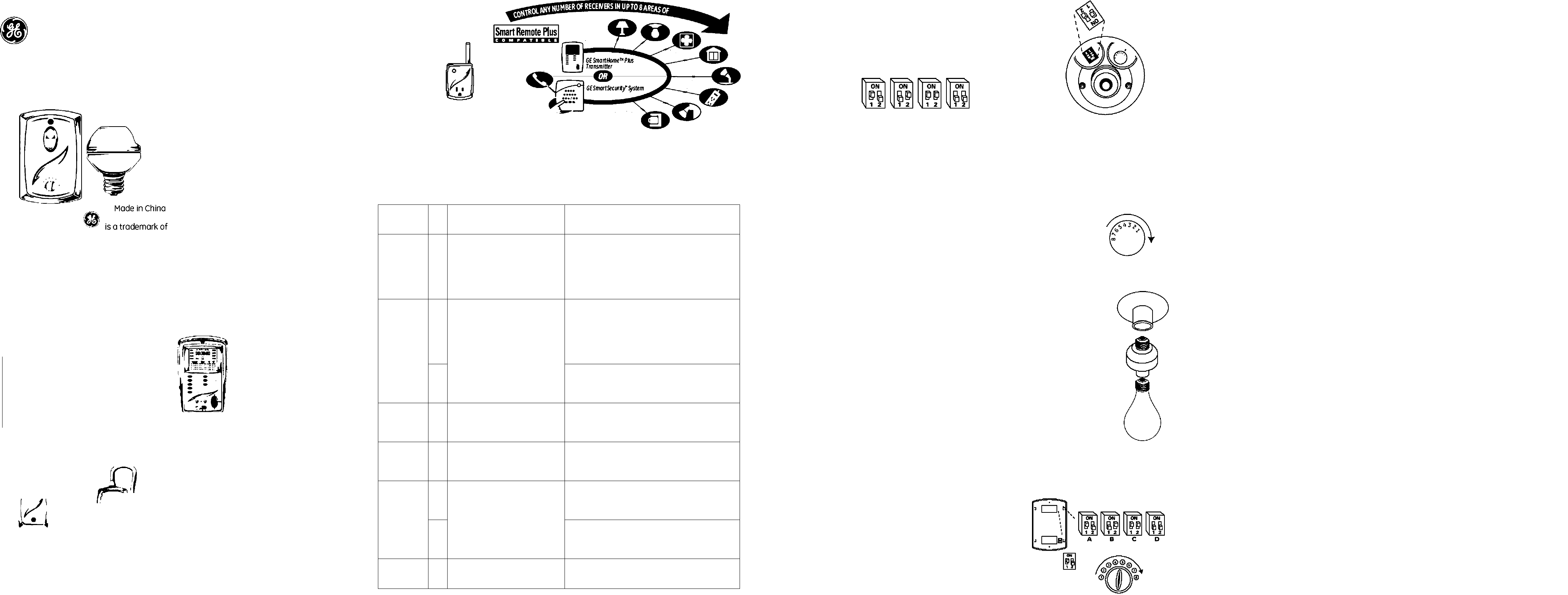
Expanding your system
The G E SmartHome™ devices operate on any of 8 user-settable channels. The channels are easy to set /
adjust-with the simple turn of a knob. Set upyour 6 E SmartHome™ by purchasing as many transmitters
and receivers as you need. The following table isjust one example of howyou can configure your
SmartHome™ system:
Area CH Transmitters
Receivers
Bedroom 1 Bedside-Wall Mount Control
Entrance-Wall Mount Control
(2) Bedside Lamps - (2) Socket Adapters
Corner Torchiere -1 ndoor Outlet Adapter
Overhead Light Fixture - Wall Switch
Entertainment System -1 ndoor Outlet Adapter
Living Room 2 Coffee Table - Timer/Controller
Entrance-Wall Mount Control
(2) End Table Lamps - (2) Socket Adapters
Overhead Light Fixture - Wall Switch
Entertainment System -1 ndoor Outlet Adapter
Christmas Tree - Indoor Outlet Adapter
3 Window Santa - Indoor Outlet Adapter
Lighted Poinsettia - Indoor Outlet Adapter
Basement 4 Entrance-Wall Mount Control (4) Overhead Can Fixtures - (4) Socket Adapters
(2) Fluorescent Fixtures - (2) 1 ndoor Outlet Adapters
Garage 5 Entrance-Wall Mount Control (2) Huorescent Fixtures -(2) Outdoor Outlet Adapters
O/erhead Light Fixture - Wall Switch
Outdoor 6 Foyer-Wall Mount Control
Car Keys-K^ Chain Remote
Entiy Light-Wall Switch
Coach Lantern-Wall Switch
7 Christmas Lights - Outdoor Outlet Adapter
Yard Santa - Outdoor Outlet Adapter
Kitchen 8 Entrance-Wall Mount Control Coffee Maker- Indoor Outlet Adapter
Operating Instructions ■ Socket Adapter
FOR INDOOR USE ONLY
ITurn the unit upside down and find the slot labeled HOUSE CODE.
2. Set the HOUSE CODE to any one of the following settings:
A B C D
NOTE: Make sure ALL you r GE Smart Home™ devices have the same HOUSE CODE setting. The transmitters
WILL NOT control the receivers if they have different HOUSE CODE settings.
IMPORTANT! HOUSE CODES help eliminate interference (devices randomly turn on/ off).
If you experience interference, change the HOUSE CODE on all your GE SmartHome™ Plus transmitters
and receivers to a different setting.
3. Keeping the unit upside down, set the CHANNEL by using the knob as shown.
NOTE: If you set your Socket Adapter to CHAN NEL1, the unit can be controlled
usi ng any transmitter set to CHAN NEL 1. If you setyour Socket Adapter to
CHAN N EL 2, the unit can be controlled using any transmitter set to CHAN N EL 2... and so on
IMPORTANTIAtransmitterwillcontrol a receiver ONLY if they have the same
HOUSE CODE and CHAN NEL settings.
4. Remove power from the lamp socket.
5. Screw the Socket Adapter into a 125VAC socket.
6. Screw the light bulb you wish to control into the Socket Adapter as shown.
7. Apply power to the lamp socket.
The following ore examples of devices you can control with your Socket Adapter:
o o o
LAMP
ENERGy-SAmG ms
CBLINGim
CAUTION: WHEN THE INDICATOR LIGHT IS ON, THE OUTPUT SOCKET IS POWERED.
DO NOT SCREW / UNSCREW BULBS INTO / FROM THE SOCKET ONCE IT IS POWERED.
Operating Instructions-Wall Mount Control
1. Find the slot labeled HOUSE CODE on the back of the unit.
2. Set the HOUSE CODE to any one of the settings shown.
3. Set the CHANNEL by using the knob on front as shown.
NOTE: If you setyour Wall Mount Control to CHANN EL 1, the unit can control
any receiver set to CHANNEL 1. If you setyour Wall Mount Control to
CHAN N EL 2, the unit can control any receiver set to CHANNEL 2.. and so on.
4. Mounting
NOTE: Mounting the Wall Mount Control on masoniy or metal walls may degrade the functional range.
Tape Mounting
A. Make sure surfaces are free of dust, oil and other substances that could affect adhesion.
B. Attach the double-sided tape to back of the Wall Mount Control housing.
C. Press tape firmly to the mounting surface.
Screw Mounting
A. Using a slotted screwdriver, remove the faceplate of the Wall Mount Control.
B. Place the detached back plate where desired and mark screw locations.
C. Insert the mounting screws into the back plate holes and screw into place.
D. Replace the Wa II Mount Control faceplate.
5. Use the toggle button to activate the Wall Mount Control (ON/OFF operation) Make sure
to press firmly and for a minimum of 1 second for best results An indicator lights RED when
a signal is sent.
6. Using anyof thereceiverssettothesameCHANNELond HOUSE CODE, test the installation by using the
ON and OFF buttons
If your unit does not work properly or if you want additional assistance, please call 1-800-654-8483. We would
be happy to anaver ALL of your guestions. Visit us on the web at www.GESmartHome.com to download
application notes, manuals and to find out more about the GE SmartHome™ product line!
Specifications
Wall Mount Control
Battery Type
...........................................................................
Use ONLY A23 (12V) A(kaline
NOTE: The functional range will decrease as the battery wea rs out so ma ke sure to replace the battery
every 6 months for best results.
Socket Adpoter
FOR INDOOR USE ONLY
DO NOTEXCEEDELEGRICAL RATINGS
Electrical Rating .................................................................................................. 120V, 60Hz
Maximum Tungsten Load ................................................................................................. 200W
‘Functional range may be adversely affected by one or more of the following factors: weather, radio
freguency interference, lew transmitter battery and obstructions between the transmitter and receiver.
This device complies with Part 15 of the FCC rules. Operation is subject to the following two conditions:
1. This device may not cause harmful interference, and:
2. This device must accept any interference received, includi ng interference that may cause undesired
operation.
CAUTION: Changes or modilications not expressly approved by the party responsible for compliance could
void the user's authority to operate the eguipment.
90 DAY LI MITE D WARRANTY; Jasco Products Company wo rrants this product to be free from manufacturing defects fer a period of ninety days from the
crig inal date of consumer pure hose. This warran V is limited \o the repair cr replacement of this product only and does not extend to consequential or
inc dental damoge to other products that may be used with this unit. Th is worranty is in lieu of all otherworranties express cr implied. Some states do
not allovv limitotions on hovv long an implied worranty losts cr permit the exc lusbn or limitaticn of inc dental or conseq uential damoges, so the above
limitotions may not apply to you. Thiswanrontygivesyouspecificrightsandyou mayolsohaveotherrightswhichvoryfromstatetostate. Ifunit
should pro/eaefectivewithin thewarranty perial. return prepaidwrth dated proof of purchase to:
Jasco Products Company. 311 N.W. 122nd, Oklahoma City. OK. 73114
 (1 pages)
 Manymanuals.com
 Manymanuals.de
 Manymanuals.fr
 Manymanuals.it
 Manymanuals.pl
 Manymanuals.cz
 Manymanuals.es
 Manymanuals-pt.com
Commentaires sur ces manuels