Ge ZE2160SF Manuel d'utilisateur

Naviguer en ligne ou télécharger Manuel d'utilisateur pour Micro-ondes Ge ZE2160SF. GE ZE2160SF User Manual [fr] Manuel d'utilisatio

  • Télécharger
  • Ajouter à mon manuel
  • Imprimer
  • Page
    / 4
  • Table des matières
  • MARQUE LIVRES
  • Noté. / 5. Basé sur avis des utilisateurs
Vue de la page 0
PART QUANTITY
Trim Frame 1
Bottom Duct 1
Top Bracket 1
Phillips Round-Head 36
Screws (27 bronze,
9 color-matched,
24 required for
installation)
Phillips Flat-Head 12
Screws (2 required for
installation)
Anti-Tip Bracket 1
Bottom Bracket 1
Template 1
PARTS INCLUDED
Questions? Call GE Answer Center at 800.626.2000 or Visit our Website at: www.GEAppliances.com
READ CAREFULLY.
KEEP THESE INSTRUCTIONS
.
Installation Built-In Trim Kits
Instructions
JX2127 and JX2130
Read these instructions completely and carefully.
IMPORTANT – Save these
instructions for local inspector’s use.
IMPORTANT – Observe all
governing codes and ordinances.
Note to Installer – Be sure to leave these
instructions with the Consumer.
Note to Consumer – Keep these instructions
for future reference.
For easier installation and personal safety, we
recommend that two people install this microwave oven.
Unplug the microwave oven before attempting
installation of this kit.
BEFORE YOU BEGIN
Skill level Installation of this appliance requires basic
mechanical and electrical skills.
Completion time – 1-3 hours
Proper installation is the responsibility of the installer.
Product failure due to improper installation is not
covered under the Warranty.
This kit is UL listed for installation alone or over
any General Electric/Hotpoint/RCA single electric
wall oven.
TOOLS YOU WILL NEED
#2 Phillips screwdriver
Pencil
Tape measure
Awl or punch
Drill with
7
64bit or #35
1
FOR YOUR SAFETY:
WARNING Before beginning the
installation, switch power off at service panel and lock
the service disconnecting means to prevent power
from being switched on accidentally. When the service
disconnecting means cannot be locked, securely fasten
a prominent warning device, such as a tag, to the
service panel.
Scissors (optional)
Vue de la page 0
1 2 3 4

Résumé du contenu

Page 1 - Instructions

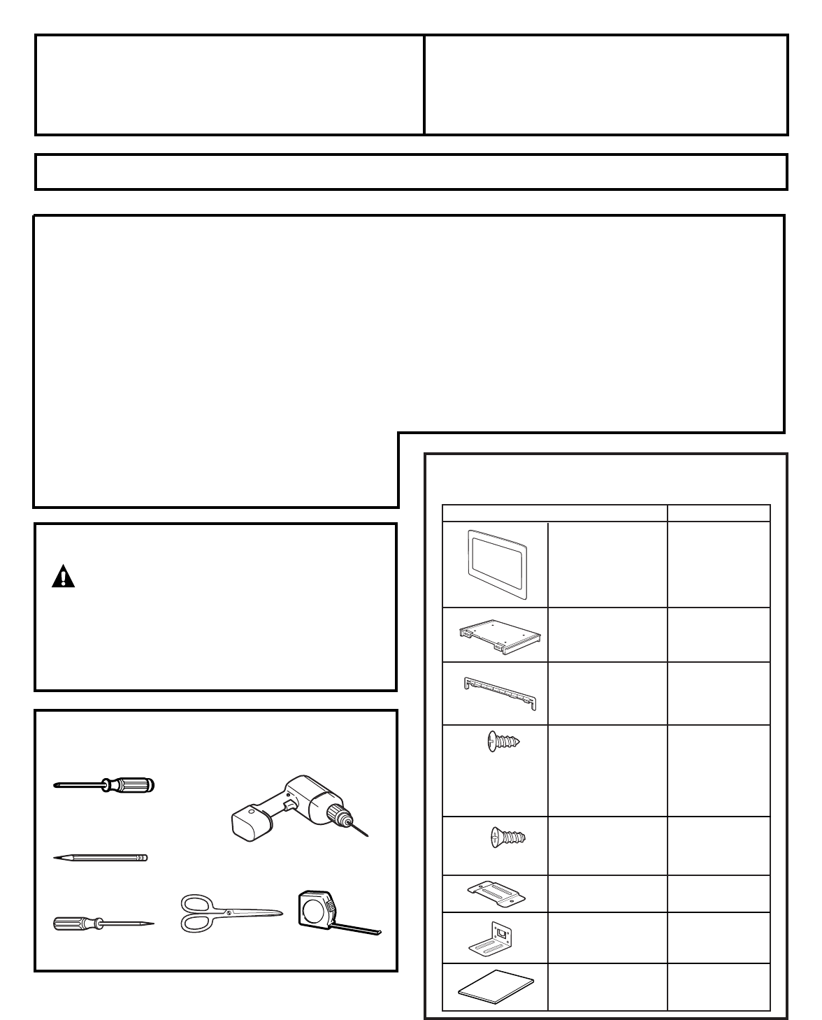
PART QUANTITYTrim Frame 1Bottom Duct 1Top Bracket 1Phillips Round-Head 36Screws (27 bronze,9 color-matched,24 required for installation)Phillips Flat-

Page 2 - Installation Instructions

2CUTOUT DIMENSIONS* Min. depth with receptacle outside cabinet 191⁄2″Min. depth with receptacle inside cabinet 22″Installation InstructionsModels 27″

Page 3

3Installation InstructionsINSTALL THE ANTI-TIP BRACKET3Draw a line on the cutout floor at the center ofthe cutout, and extend the line 1⁄2″ down the f

Page 4

4Installation InstructionsPlace the top bracket on the top of the microwaveoven, with the tabs on the top and sides of thebracket fitting squarely aga

Commentaires sur ces manuels

Pas de commentaire