Ge EER3000 Manuel d'utilisateur
Naviguer en ligne ou télécharger Manuel d'utilisateur pour Radio Ge EER3000. GE EER3000 User Manual Manuel d'utilisatio
- Page / 12
- Table des matières
- MARQUE LIVRES
Noté. / 5. Basé sur avis des utilisateurs
1
229C4053P545-5
31-10556-5 06-04 JR
EER3000, EER3001, JBP24, JBP25, JBP26, JBP35, JBP48, JBP64, JBP66, JBP67, JBP68, JBP69,
JBP71, JBP78, JBP80, JBP82, JBP83, JBP84, JBP99, JB600, JB710, JB905, JB968, JB988, JBS55
Installation
Free-Standing
Instructions
Electric Ranges
BEFORE YOU BEGIN
Read these instructions completely
and carefully.
•
IMPORTANT
— Save these
instructions for local inspector’s use.
•
IMPORTANT
— Observe all
governing codes and ordinances.
• Note to Installer – Be sure to leave these
instructions with the Consumer.
• Note to Consumer – Keep these
instructions for future reference.
• Skill level – Installation of this appliance
requires basic mechanical skills.
• Completion time – 1 to 3 hours
• Proper installation is the responsibility of
the installer.
• Product failure due to improper installation
is not covered under the Warranty.
WARNING — This appliance must
be properly grounded.
FOR YOUR SAFETY:
WARNING — Before beginning the
installation, switch power off at service panel
and lock the service disconnecting means to
prevent power from being switched on
accidentally. When the service disconnecting
means cannot be locked, securely fasten a
prominent warning device, such as a tag, to
the service panel.
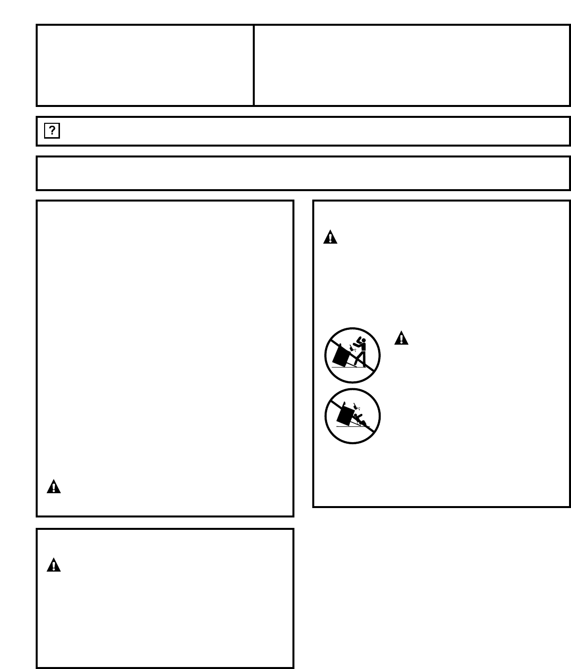
ANTI-TIP DEVICE
WARNING
— To reduce the risk
of tipping, the appliance must be secured by
properly installed Anti-Tip bracket packed
with this appliance.
If the Anti-Tip device supplied with the range
does not fit this application, use the universal
Anti-Tip device WB2X7909.
WARNING
—
• All ranges can tip
• Injury to persons could result
• Install Anti-Tip bracket packed
with range
• See Installation Instructions
If you pull the range out and away from the
wall for any reason, make sure the Anti-Tip
bracket is engaged when the range is pushed
back against the wall.
Questions? Call 800.GE.CARES (800.432.2737) or Visit our Website at: www.GEAppliances.com
Résumé du contenu
Page 1 - Instructions
1229C4053P545-531-10556-5 06-04 JREER3000, EER3001, JBP24, JBP25, JBP26, JBP35, JBP48, JBP64, JBP66, JBP67, JBP68, JBP69,JBP71, JBP78, JBP80, JBP82, J
Page 3
11Notes
Page 4 - ELECTRICAL CONNECTIONS
12Printed in the United States
Page 5
TOOLS YOU WILL NEEDFOR YOUR SAFETY:All rough-in and spacing dimensions must bemet for safe use of your range. Electricity tothe range can be disconnec
Page 6
3Installation InstructionsPREPARE THE OPENINGSee illustrations for all rough-in and spacingdimensions.The range may be placed with 0” clearance(flush)
Page 7
4Installation InstructionsELECTRICAL CONNECTIONSUse only a 3-conductor or a 4-conductor UL-listed range cord. These cords may beprovided with ring ter
Page 8 - INSTALL THE RANGE
5Installation InstructionsPOWER CORD AND STRAIN RELIEF INSTALLATIONRemove the wire cover (on the back ofthe range) by removing five (5) screwsusing a
Page 9
6Installation InstructionsELECTRICAL CONNECTIONS (CONT.)4-WIRE POWER CORDINSTALLATIONWARNING: The neutral wire of the supply circuit must be connected
Page 10
7Installation Instructions3-WIRE CONDUIT INSTALLATIONLoosen the 3 lower terminal screws fromthe terminal block. Insert the center barewire (white/neut
Page 11
8Installation InstructionsINSTALL THE RANGEANTI-TIP DEVICE INSTALLATIONAn Anti-Tip bracket is supplied withinstructions for installation in a variety
Page 12 - Printed in the United States
LEVEL THE RANGEInstall the oven shelves in the oven andposition the range where it will be installed.Check for levelness byplacing a spirit level or a
Produits connexes et manuels pour Radio Ge EER3000
Radio Ge 49-80602 Manuel d'utilisateur

 (104 pages)
(104 pages)
Radio Ge 49-8779 Manuel d'utilisateur
(60 pages)
(60 pages)
Radio Ge 49-80038 Manuel d'utilisateur
(28 pages)
(28 pages)
Radio Ge 164D3333P185-1 Manuel d'utilisateur
(36 pages)
(36 pages)
Radio Ge 49-80535-1 Manuel d'utilisateur
(36 pages)
(36 pages)
Radio Ge 10-95 CG Manuel d'utilisateur
(44 pages)
(44 pages)
Radio Ge 164D3333P071 Manuel d'utilisateur
(48 pages)
(48 pages)
Radio Ge 49-80575-1 Manuel d'utilisateur
(104 pages)
(104 pages)
Radio Ge EGR3000 Manuel d'utilisateur
(52 pages)
(52 pages)
Radio Ge 49-8255 Manuel d'utilisateur
(32 pages)
(32 pages)
Radio Ge EER2000 Manuel d'utilisateur
(12 pages)
(12 pages)
Radio Ge 49-8338 Manuel d'utilisateur
(49 pages)
(49 pages)
© 2020, manymanuals.fr. Tous droits réservés | 0.681 s |
 Manymanuals.com
 Manymanuals.de
 Manymanuals.fr
 Manymanuals.it
 Manymanuals.pl
 Manymanuals.cz
 Manymanuals.es
 Manymanuals-pt.com
Commentaires sur ces manuels